| Home Page
Bus
Chute / Shell
Sensor
Power
Data Processing
Photos/Schematics
Results
Contact
|
|
|
How We Dealt With Sensor Data
The PX-40 sensor outputs voltage. That voltage must be converted to a format, which can be transmitted to the ground station. The CanSat5 has redundant processing schemes for its PX-40 sensor data.
That is, we decided to send the same sensor data in two different data formats.
1) We decided to use a Voltage Controlled Oscillator (VCO) to convert voltage into frequency.
2) We also decided to use ADC0831, an Analog-to-Digital chip to convert voltage to an 8 Bit Scaling Factor.
Both frequency data and 8bit scaling factor can be post-processed after receipt by the Ground Station to be converted to ambient pressure data.
|
| |
|
Voltage Controlled Oscillator

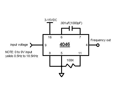
VCO Schematic with the 4046
We used the MC14046B chip by Motorola Semiconductor. The chip has two phase comparators, a VCO, a source follower, and a zener diode built in. The only part we were concerned with was only the VCO part of the chip. You can download the spec sheet and see that the pins we used correspond to only the VCO part of the chip.
The 4046 chip can take in voltage and convert it to frequency. We initially used PBASIC language's "pulsin" command under PBASIC's Digital I/O instruction set. Click here to download BASIC Stamp Manuals. We soon found the frequency limit of the "pulsin" command too constraining. So we set out to write our own routine in PBASIC to count the number of cycles in a period. The software resides as a subroutine in the communications code.
MC14046B spec sheet

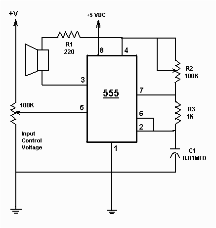
VCO Schematic with the 555 Timer
As a side note, we initially attempted to make a VCO with a 555 Timer chip. The diagram you see above was recreated from Forrest Mims' "Timer, OpAmp & Optoelectronic Circuits & Projects" book published by Radio Shack. The problem we encountered with the 555 version of the VCO was its limited input voltage range. We tried changing the values of the resistors and the capacitors, but that did not seem to affect or extend the voltage range.
If you've had success working with a 555 in making a VCO with input voltage range of 0 to 5 volts, we'd like to hear how you did it...
NE555 spec sheet
|
| |
|
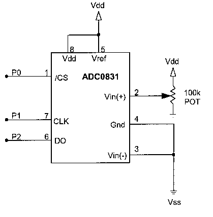
 Analog to 8 bit Scaling Conversion Schematic with the ADC0831
ADC0831 Chip
We used the ADC0831 chip to convert voltage level to an 8bit scaling factor for the voltage differential range of 5.0 volts. The ADC0831 is very simple to use, and thus is popular among the amateur electronics people. The schematic on the left depicts a circuit that uses a 100KOhm potenetiometer as sensor model for varying the voltage.
An accompanying software was written for the BASIC Stamp to control the ADC chip to read in an analog signal and "shift out" or read out corresponding 8bits of data back to Stamp to be sent to the ground station.
ADC0831 spec sheet
|
| |
|
|
|
|
|


