|
These are photos of our CanSat at various stages.
The photo size was purposefully kept big enough to see details. We hope to add more photos soon after Albert takes his make-up Final Exam. (The photographs were taken by Albert.)
|
|
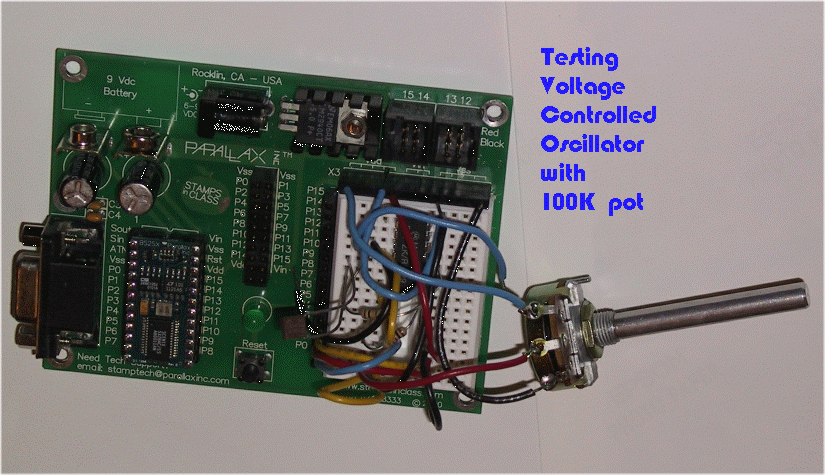
Above, we are using a potentiometer as a subsitute for our pressure sensor to test our circuit and software in the BASIC Stamp. Our sensor outputs voltage levels between 0.5 volts and 4.5 volts. The proto-board you see in the picture is Parallax's Board of Education. The software code being tested is a pulse cycle duration counter . As you can see in the photo, we used an extra BS2SX for this test.
|
|
|
|
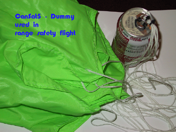
Above, the dummy that was considered lost after its maiden flight. Here, you see it after its recovery.
The dummy is a Coke can filled with rocks. The parachute is attached to the can's stay tab with plastic fasteners.
|
|
|
|
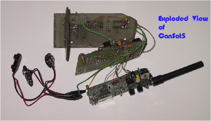
Above, you see the CanSat 5 has three boards. The top board is the payload. The middle board has the microcontroller, DTMF tranceiver, and the voltage regulator. The bottom board is the FRS radio. Note the three 9volt battery clips. One of them is the good one with hard plastic case. The other two clips are covered by flimsy vinyl, that seems like it can rip apart when trying to snap off the batteries.
|
|
|
|
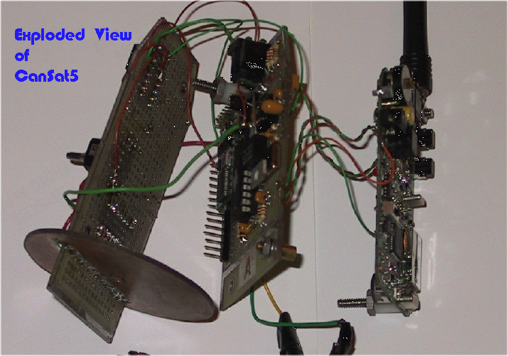
Another Exploded View
|
|
|
|
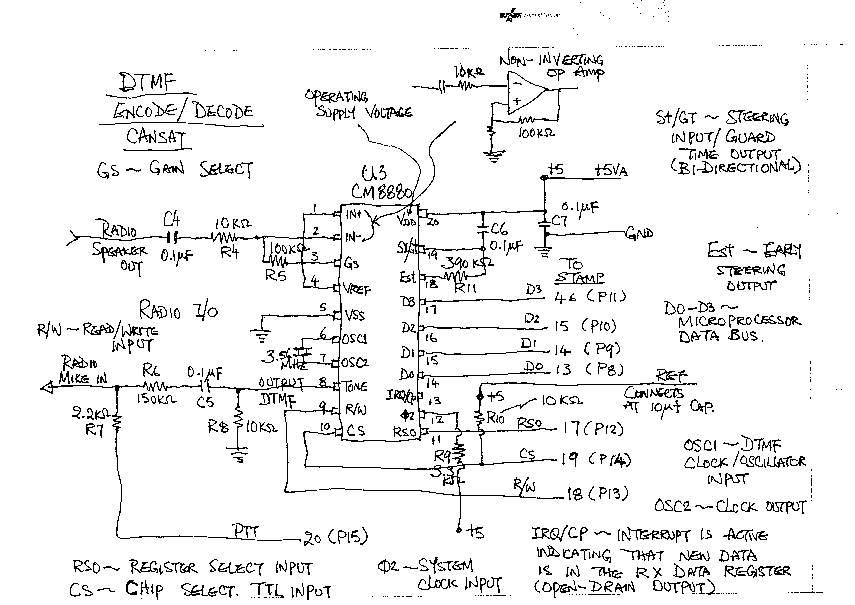
DTMF-centric View of Electrical Conncections (above)
|
|
|
|
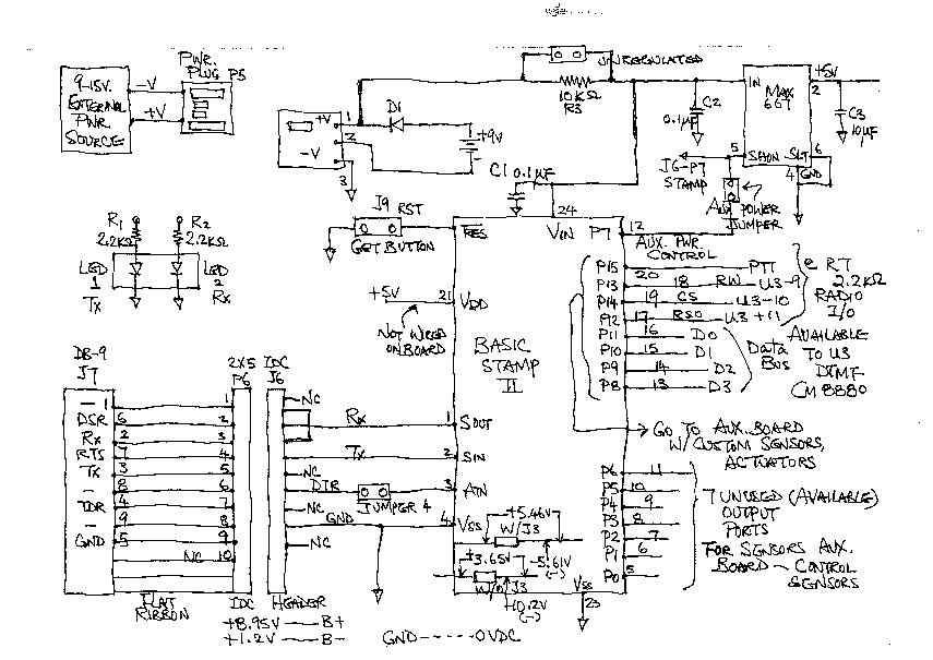
BASIC Stamp-centric View of Electrical Connections (above)
|
|
|
|
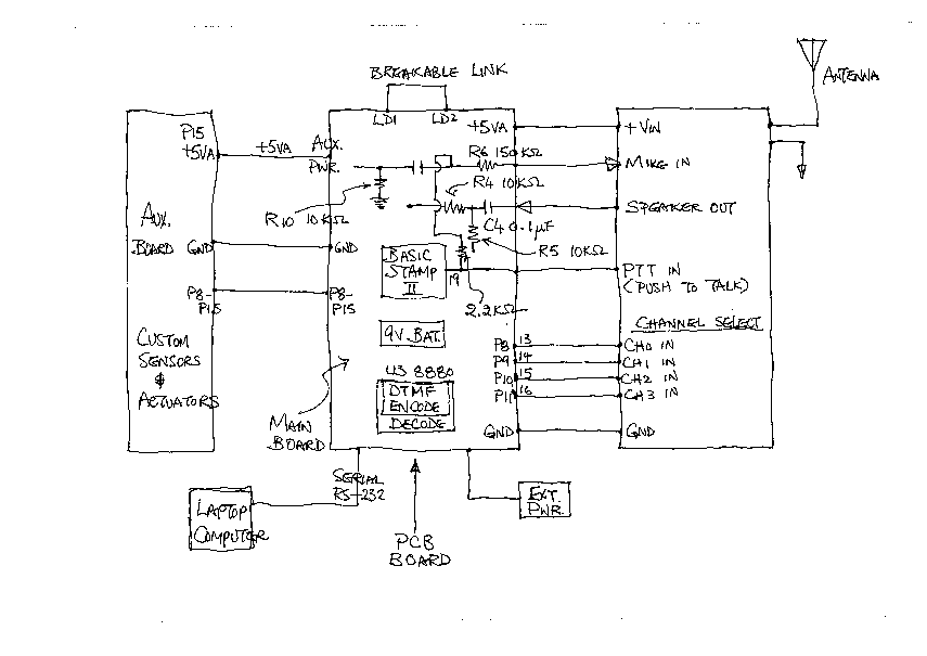
Bird's Eye View of the Electrical Connections Between the Three Boards (above)
|
|
|
|
|
|
|
|
|
|
|
|
|
|
|


